2012
Click links below for the relevant section
December 2012
-
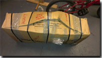
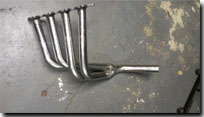
Finally, a week into December the parts I had been waiting for arrived in a box that wasn’t quite as large as I was expecting, seeing as it was supposed to have the new drive shafts, exhaust manifold, fuel tank, brake master cylinder, handbrake adjuster and wishbone spacers. However once unpacked and checking that everything was undamaged I was pleased that I could now make some progress...once I got some free time in the garage.
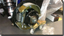
The first job was to check that the drive shafts were the correct length and would allow the hubs to be fitted. The new ones protrude out from the edge of the upright plate by around 15mm which are then compressed slightly when the hub is installed and bolted to the backing plates for the drums. Once these were fitted I could then get round to fitting the brake shoes, new rear brake cylinders, fixing kit and connecting up the handbrake cable using the adjuster which also came in the box of parts.
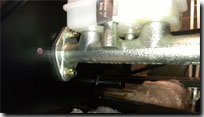
Checking the master cylinder; which is a tandem cylinder operating both the front and rear brakes, the mounting holes were in the vertical plane rather than the horizontal holes that are pre-drilled in the footwell bulkhead. Speaking to Barry at Fury Sportscars this is now how they are supplied but used to be horizontal, the only option is to drill new holes and fill in the pre-drilled holes. Depending on the amount of flexing in the bulkhead wall, I may use these holes to attach a slightly thicker plate to help reduce this flexing that I have seen others report on their builds. When connecting up the pedal box to the fitted cylinder I noticed the clevis was contacting on the cut out in the pedal so I made the cut out slightly larger to give the clevis more clearance, allowing more movement on the pedal.
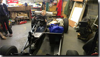
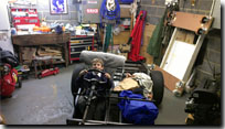
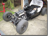
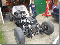
With the master cylinder now fitted I could finally finish the connections for the front and rear brake lines and install the hydraulic operated brake light switch to one of the t-couplings in the front line. Now with the front wishbones spacers, I could finally fit the front wishbones, uprights, brake discs and calipers and connect this up to the steering rack. With two days spent in the garage the car has been transformed and is now on its build wheels (the Sierra donor ones) and allowed my boys to sit in the car and be pushed back and forwards checking out the steering.
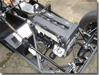
With a few days off over Christmas I decided to tackle trial fitting the engine and drilling the mounting points. Starting the traditional way of slinging the engine and gearbox at 45 degrees and dropping into the gap was proving difficult trying to do this by myself so I tried an alternative method. Leaving the engine in the trolley I had made, I lifted the front of the chassis off the ground using the hoist, wheeled the engine underneath and slowly lowered the chassis over the engine which was much easier. Having drilled the mounting points and checking the clearance all round I wasn’t happy with the first positioning as the nearside of the gearbox seemed far too close to the chassis rail and would occasionally rub against it. After a few more hours of re-positioning I have now moved it back by about 15mm which seems tight around the bell housing but is a far better location for the gearbox mounting which does seem to be slightly offset with the tail end nearer the drivers side but only slightly. I will have to get the original holes I drilled welded over but I'm now much happier with the positioning.
Back to top
November 2012
-
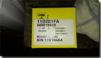
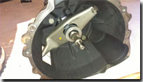
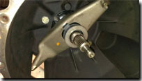
For the majority of this month I have still been waiting for all the parts from Steve at Fury Sportscars which is really holding back progress at the moment when I do get time to go into the garage and do things. One thing that I did manage to get round to was to fit the bell housing to the gearbox followed by the clutch arm and release bearing. On looking at the release bearing it was obvious that one of the plastic locking tangs was broken off which meant that it wouldn’t hold onto the arm properly. Unfortunately I had bought this back in July from my local motor factors but hadn’t inspected it after getting it (lesson learned) but thought I would give it a try and to their credit they were happy to replace it...but they could no longer get stock of the CCT133. Looking up the part numbers again they found the LUX alternative (500018410) which was more expensive but they replaced it for the cost of the original one ordered, result and also the LUX version is better as it has metal locking tangs to hold it to the clutch arm so better all round.
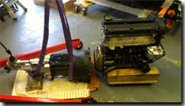
Once that was fitted I mated up the gearbox to the engine, although I only aligned the clutch plate up by eye the gearbox went on fairly easily using my engine hoist to hold the gearbox and jiggle the gearbox into the correct position. To make fitting the engine to the chassis easier I will leave the Plenum and other ancillaries off the engine for now and fit the remaining items once fully installed.
Back to top
October 2012
-
Not having the drive shafts to fit to the rear stopped me from fitting the rear brakes and hubs and therefore the rear wheels too. Also when speaking to Steve at Fury Sports cars I asked a few questions that had been bothering me and found out he hadn’t supplied the spacers for the front upper wishbones or the handbrake adjuster so I couldn't progress the handbrake or fit the front suspension either. Also I was still waiting for the exhaust manifold and fuel tank so that put a stop to progress for this month really while I waited for these parts.
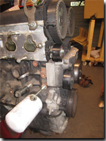
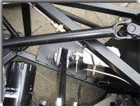
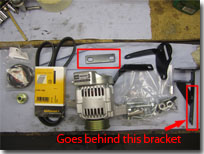
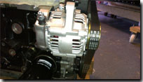
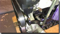
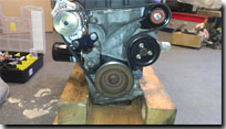
One thing I did do was fit the alternator kit to the engine that I had got previously from Kitspares in Newark. This came with no instructions but would be fairly simple and obvious to fit…and it was until I was left with a flat bracket which I couldn’t figure out where it went? A quick search on the internet revealed that others too had been confused by this bracket and assumed that it was just a spare or alternative solution for different versions. Not happy with this answer I phoned Richard at Kitspares and found out that it is a spacer to go behind the main alternator bracket (see Picture 1). Once fitted I suppose it is obvious really but didn’t seem it at the time!!! Although the kit is quite expensive, it is an easier option for someone without welding facilities and does allow for the original water pump to be used as it allows it to rotate in the correct direction.
Other than that, what with work and the lack of bits I haven’t made much progress again this month, hopefully some better news next month….
Back to top
September 2012
-
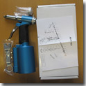
Just before leaving for a family holiday at the end of August I took all the drilled and de-burred aluminium panels to Alpha Powdercoating in Peterborough, now in September I collected the panels and sorted through them ready to fit to the chassis. Before fitting, I ran a bead of silicone sealant along the face that would be in contact with the chassis, one to protect the panel and chassis slightly from the different material causing corrosion but also to provide an element of weather proofing. After running the bead I fixed the panels in place with the ‘Skin Pins’ and then riveted them to the chassis using a hydraulic/pneumatic riveter. If you are going to be doing a fair amount of riveting it is very worthwhile purchasing one of these, otherwise hand riveting the few hundred rivets by hand will really be hard work and the hydraulic riveter provides a consistent, level and solid fastening. Don’t be tempted to buy a cheap version (£25ish) from e-bay as these will probably not last for the amount of rivets you will be fixing, instead for ten pounds more you can get a fairly decent one without breaking the bank from ‘Thorite’.
Starting with the passenger foot-well panel, then onto the inner/tunnel panels, the outer panels followed by the floor panels and finally I will fit the rear panels but before I fit those I am waiting to finally fit the drive shafts and drop the chassis onto its wheels so I can access to bolts easily should I need to. All these are fitted with 4mm rivets except for the floor panels which are fitted with the heavier duty 4.8mm flange rivets which help to support the weight put on the floor panels.
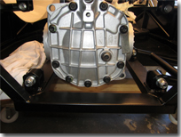
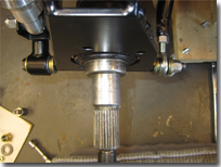
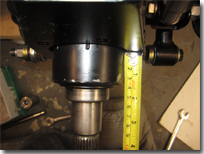
Back to topThe reason why I haven’t fitted the wheels yet is because when I fitted the rear drive shafts properly and tried to fit the hubs it was obvious that one shaft was too long and the other too short (yes I tried them either side as well). When the differential fits into the chassis the locations for the shafts is slightly offset so the shafts need to be of different lengths, which they are but just not by the right amounts. This document shows what I mean.
August 2012
-
For the majority of August, I spent the time I had off of work lining up the chassis panels and drilling the holes ready for riveting. This took quite a while as I wanted to take my time and do this right, measuring along the panels and ensuring that the rivet spacing's were all correct before I started to drill through. The skin pins I purchased ages ago and the windy drill powered from my compressor made this job a whole lot easier than it would have been with an electric drill and ordinary clamps. Having used these tools during my regular job I can recommend these as making life a whole lot easier. Most of the panels required some amount of 'fettling' to ensure a good fit and others such as the tunnel top panel had to have a section cut out for the handbrake to come through. Also with the tunnel top panels I fitted 'Rivnuts' so that the panels can be attached by screws to allow for easier removal should I need to and without having to drill rivets out. The reason for not having 'rivnuts' for all panels is that the panels make up some part to the overall rigidity of the chassis and you just don't get that by screwing the panels in place with regular rivnuts and screws, riveting will achieve the required stiffness. Once the panels had been drilled, de-burred and cleaned up I took them to a local Powdercoating firm, Alpha Powdercoating who did an excellent job producing a very good quality finish for a very reasonable price. Powdercoating the panels will give them a better finish and help to stop them from oxidising which can happen with Aluminium panels.
Back to top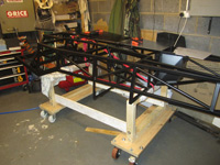
-sml.jpg)
.jpg)
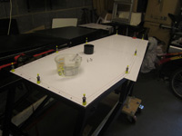
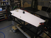
If you're wondering why there is an overhang on the floor panel, this is used to secure the side pods in place when fitting the body panels. There are others panels which will be attached once I get round to attaching the body parts.
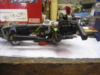
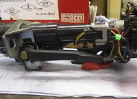
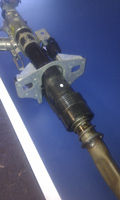
One of the other jobs done this month was to try and fit the steering column. Usually the Fury takes the none adjustable column out of the Sierra but with a bit of fabrication I was sure the adjustable version could also be used. After much playing around and a little bit of fabrication I found that by turning the fixing bracket around the opposite way and cutting down the adjuster handle it would fit. Although the height of the column will not be adjustable from the seat it can be adjusted at the moment so I can get it set up for the best position for me before fitting the dashboard.
July 2012
-
After placing my order back in April for the chassis and associated items it was finally ready for collection from Fury Sports Cars. Having booked a van to pick it all up, me and both of my boys did the three and a half hour drive down to Cranbrook in Kent. With the help of Steve and a few others around the industrial units, we managed to load the chassis, panels, suspension parts and all the other components into the van.
Whilst down in that neck of the woods I popped into Car Builder Solutions as it is only six miles from Cranbrook and picked up some of the other bits I would need for the build, brake line, hoses, pipe benders, unions etc.
.jpg)
.jpg)
.jpg)
Having unwrapped the chassis from all its bubblewrap I then trial fitted all the suspension components to check they were all there, correct and fitted ok to the chassis. With the powdercoating some items were a little tight and needed a bit of gentle persuasion to fit which did occasionally chip off a little of the powdercoat but there is not alot you can do about that, I will just have to touch up these areas with a little hammerite paint to prevent moisture getting in.
.jpg)
.jpg)
.jpg)
.jpg)
.jpg)
.jpg)
Also over this month I purchased a Plenum Chamber from Kitspares. To enable this to be fitted to the Zetec engine the original inlet manifold has to be cut down and flattened off. This then holds the original injectors and fuel rail and is secured to the plenum chamber by applying some silicon sealant to the two faces and bolting onto the engine until the sealant goes off, this is then secure and air tight to prevent leakage on the inlet ports.
Back to topJune 2012
-
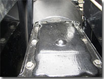
A bit more progress made on the engine overhaul, stripped the steel sump pan and aluminium base off the engine and have looked into the details of chopping the steel sump pan down for the required floor clearance once the engine is dropped into the chassis. Various options are available ranging from the cast aluminium Raceline sump available but that is £450 which at this moment in time is far too expensive.
Another option is to purchase a Zetec phase 1 or 2 sump and have that modified by Scholar Engines which would cost around the £280 mark.
The last option is to attempt to chop down the steel sump and pick up pipe that is fitted as standard on the phase 3 Zetec and have that welded up with a new steel base. The idea for this was found through trawling the internet and seeing this method highlighted on Paul's Zetec pages .
.jpg)
.jpg)
.jpg)
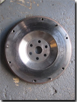
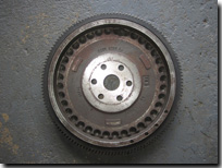
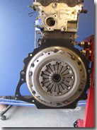
Before fitting the flywheel and clutch I slave fitted the bellhousing to see the openings that the Sierra bellhousing would leave when fitted to the Zetec. Some people say you can leave these uncovered as the draft from the flywheel stops anything going in but I would rather be safe than sorry. I drew up a template out of cardboard and then cut this out of aluminium sheet that I had lying around. Once cut out and ensuring it fitted with the bellhousing fitted I gave it a quick coat of paint to help protect it a little once installed.
.jpg)
.jpg)
.jpg)
Back to topFebruary to May 2012
-
Apologies for the lack of updates over the past few months but I have been very busy at work which has lead me to turn in my notice and start job hunting while also doing as much as I can to the donor parts and doing additional website work for other people. Unfortunately this site has been a little neglected but hopefully I should get some good news over the coming months and be able to update on progress made, both on the kit and job front!
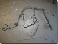
The strip down of the engine as far as I am going is now complete and have now started to source the required parts to start the rebuild. I have managed to purchase a 1.8ltr zetec flywheel from a Mk1 Focus from e-bay for £20 which I didn't think was too bad. Also managed to get an ECU, full loom and some of the sensors required to run the engine on the standard ECU
I have also purchased a complete new set of bearings for the front and rear hubs which I will replace once I receive back the modified struts from Steve at Fury Sports cars, new rear wheel brake cylinders and a front brake caliper refurbishment kit. These last two items will be sorted when I get a little time to do them.
I have replaced the timing belt and tensioner with one purchased from e-bay and while that was off I also changed the seal on the back of the waterpump which is difficult to change properly with the timing belt in place.
Over the Easter break, Chris my eldest and I took the opportunity to visit Steve at Fury Sports Cars for another look around at the cars he had in there and also to finally place my order for the chassis and other items I will need to get started. A bit like a kid in a sweet shop there were loads of bits I wanted but don't really need just yet so I ordered the chassis with all the paneling required, exhaust manifold, pedal box, fuel tank and suspension struts. The body shell can wait for now until I really need it as storage of that would be a problem. While there I also dropped off the items from the donor that are modified as part of the kit purchase; the front uprights, drive shafts, steering joint and handbrake.
Back to topBack to topJanuary 2012
-
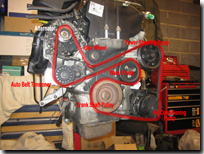
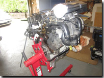
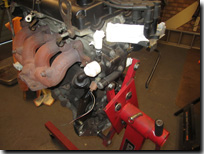
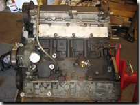
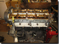
Managed to make a start on stripping the Zetec engine down this month. First thing was to strip off all the ancillaries that will not be used, the air conditioning pump, power steering pump and the auto belt tensioner. Next I stripped off the air box, inlet manifold and the injectors, from the inlet manifold I removed the single throttle body and the idle by-pass valve which I will try and use with a standard ECU. The coil pack and thermostat block were next, removed to be cleaned and will be put back on for re-assembly.
The next thing to go was the exhaust manifold which will be replaced by one supplied from Fury Sports cars, then I cleaned up the faces of all the remaining gasket and sealant. Removing the Cam Cover to reveal the twin cams which showed no real signs of wear or damage. The next job will be to remove the timing belt and replace with a new one. While that is off I will change the seal on the water pump to which is located behind the timing belt and awkward to change with the belt in situ.
2011 -


-sml.jpg)
-sml.jpg)
-sml.jpg)
-sml.jpg)
-sml.jpg)
.jpg)
.jpg)
.jpg)
_sml.jpg)
