Engine
I was never going to be using the CVH engine from the Sierra donor really as it was leaking oil through the valve stems like crazy when I collected it. I know its a fairly easy job to replace them but I always really wanted to use a zetec or something similar as they are much more reliable, economical and probably better power for the size of engine. Also, lots of people use the Zetec in their kits so information about fitting it should be easily available.
Strip Down
-
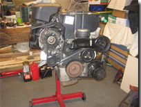
When I say strip down, with the cost of parts compared to the overall cost of the purchased engine its hardly worth doing a complete strip down of a Zetec engine. The first thing to do was take off the electrical loom and all the ancillaries that will not be needed, the power steering pump, air con pump and alternator. Also I stripped off the exhaust manifold which will eventually be replaced by the one purchased with the kit from Fury Sports Cars. While at it I also removed the inlet manifold which won't be used but I will strip off the idle bypass valve and single throttle body which I will be using (more of that later).
Back to top
Strip Down Part 2
-
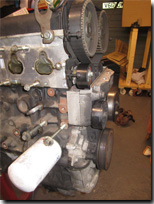
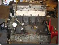
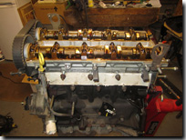
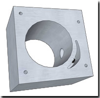
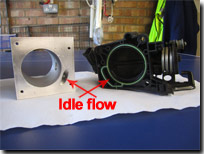
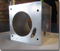
With all the ancillary components removed I gave the block a clean up and a coat of paint with the ever reliable black Hamerite. Next thing to do was change the cam belt and tensioners which are one of the few essential item to change really on a second hand Zetec, the others being the oil filter and spark plugs. While the cam belt was off I also changed the water pump seal as this is located behind the cam belt. With me attempting to use the standard Zetec/Mondeo ECU and equipment to reduce costs the question came up in conversation with Warren, my Zetec guru, about using the idle bypass valve with the single throttle body and a plenum chamber.
Warren said that most people who use the single throttle body just wedge the throttle open a fraction to create an idle flow but this is rather hit and miss and can create all sorts of problems when trying to get the engine setup and starting. So with an idea in mind I set about drawing it up into a useable design and getting one of my contacts at work to have a go at making it. The general idea is that the idle flow by-passes the butterfly valve on the throttle body goes through the face on the block to the idle by-pass valve which is controlled by the ECU. This then sends the flow back through to the entry of the plenum chamber. The result looks quite good if a little chunky but we will have to wait and see if it will work as planned.
Back to top
Sump modification
-
The options for changing the sump for the zetec range from the very expensive £450 Raceline lowered sump, the Scholar Engines modified sump at £280 or the self modification of the phase 3 sump as highlighted on Pauls Zetec Blog. With money being a bit tight I opted for the chop down of the standard phase 3 sump but if things don't work out or I suddenly win the Lottery then I may plump for one of the other options.
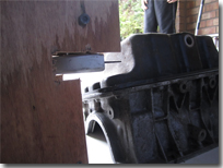
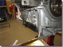
The first thing to do is set-up an angle grinder in a fixture that will allow for the sump to be cut virtually all the way around. The last part will need to be cut across with a hacksaw. Attaching the steel sump to the aluminium upper part allows the sump to sit at the correct angle for cutting down.
The next step to take is to fabricate the sidewall that is going to help recover some of the lost capacity from removing the sump base. This is done ny bending into shape a piece of steel to go around the stepped end of the sump so that it is level with the sidewalls of the remaining part of the sump. You also need to remember to cut out the old sump plug location point and make a cutout for it to be put in a new location on the modified sump at the lowest point.
As part of the modification the pickup pipe also needs to be cut down and effectively raised up from the bottom of the sump. I have placed it about 10mm from the base which from what I could work out was how far it was above the original sump base. The aluminium top section of the sump also needs a little modification to enable the pipe sit within the base.
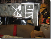
Finally, the base is welded on and the baffles put in place to cater for the surges forward and aft during braking and acceleration, hopefully this should stop any cavitation of the pump during these times and provide enough oil to keep the engine sufficiently lubricated.
Finally, the last thing to do was paint the sump to protect it from the elements and then attack the aluminium half of the sump block with a hacksaw and angle grinder to allow the Sierra starter motor to be used with the original bell housing.
Alternator
-
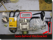
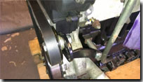
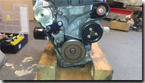
The original alternator fitted to the Zetec engine is too large and provides more power than would be needed for the Fury. Also, the drive belt to drive the alternator also runs around the power steering pump, Air Conditioning Pump and Water Pump but two of these I will be removing as they are no longer required. The best option I found was an alternative kit provided by Kitspares which comprises of a small 40 amp Denso alternator, mounting brackets, idler wheel and the belt needed to run on a Blacktop Zetec which drives the original water pump in the correct direction.
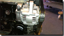
Having removed the pumps no longer required during the strip down it was a simple matter of fitting the brackets, idler wheel and alternator and then running the drive belt around theses and also onto the water pump. Overall it is a very neat installation and will hopefully provide a trouble free method of providing the power I need. The only problem I found when fitting the brackets was that I had one plate left over and couldn't see what it was for. After a quick call to kit spares they told me that this is a spacer bar for the main mounting bracket, apparently I am not the first person to ask this question.
Plenum Chamber
-
Using the original plenum chamber in the Fury is not an option as the space under the bonnet and the orientation of the inlet just wouldn't work so I did some research on my options over the internet and also when attending some of the kit car shows. There are four main options when it comes to the inlet/fuelling side:
- Carburetors
- Bike throttle bodies with injector plate
- Jenvey/Omex or other after market throttle body kit
- Plenum Chamber with single/original throttle body
There are various pros and cons with each set-up and each one I looked at to decide which would the best way forward for me.
- Carburetors - A simple set up initially but does need to have a rolling road session to get ideal running. Not as reliable as electronic fuel injection in my opinion and harder to meet emissions requirements at the IVA test.
- Individual Bike Throttle bodies - Much like the Carb set up, generally needs a rolling road session to get a good set up to allow it to pass the IVA emissions test but does provide good power and there are quite alot of options. Something I may look at in the future once IVA test passed.
- Jenvey/Omex after market kit - A step on from the bike throttle body set up with dedicated electronics and mapping. Again does need a rolling road set up and provides good power but are generally quite an expensive initial outlay.
- A plenum chamber and single throttle body using the original Ford ECU - This is the option I have chosen for now as it is a proven method which is reliable and easy to pass the IVA emission test with out the need for a rolling road session. The only difficulty is having a matching ECU, PATS sensor and key and also working out the wiring.
Having looked at the various options, kitspares again provided a neat solution to the single plenum chamber method which used the original Ford Mondeo single throttle body, inlet plate and fuel injectors. This set up also allowed the use of the original Ford ECU to be used.
When I went to Kitspares to purchase various parts including the plenum chamber and alternator kit I also took along my original inlet manifold which I had removed the majority of the inlet pipes which leaves an almost flat plate. Whilst there they placed the plate on a belt sander and removed the remaining parts of the inlet tubes leaving the face flush which is then stuck to the plenum chamber using a gasket sealant. This plate also houses the injectors and so provides a neat solution to mounting the injectors and fuel rail.
One problem I did find with the Kitspares plenum chamber was with the original fuel inlet pipe (which bends round through 180 degrees), is that it blocks off the breather pipe on the CAM cover or if turned around it wouldn't fit due to one of the braces on the plenum. To get around this Kitspares also sell a pipe that comes straight out from the fuel rail but you do loose the Schrader valve used to test for fuel pressure.
Clutch, Gearbox and Bell housing
-
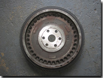
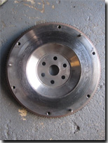
The Zetec engine I will be using is originally from a 1999 Ford Mondeo and was fitted with the 2.0ltr flywheel and clutch which is quite heavy. An easy and fairly cheep upgrade is to remove the flywheel and clutch and replace with the Mk1 Focus 1.8ltr flywheel which is about 2kg lighter and can also be fitted with a slightly smaller clutch. The flywheel I managed to buy from e-bay for £20 and I fitted a new clutch too while I had easy access. This flywheel can be used easily with the Type 9/Sierra bell housing and the Lucas LRS707 Starter motor without the need to add any spacing. I then fitted the new clutch which is the clutch from a 1.8Ltr Mondeo which has the required number of splines to fit the Type9 input shaft (23) and fits the bolt pattern of the 1.8 Focus flywheel. before fitting this I made a dust shield out of Aluminium sheet to prevent dirt ingress into the bell housing.
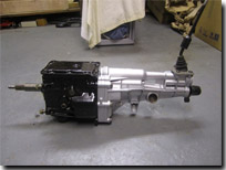
Once I had removed the gearbox from the Sierra donor, I cleaned it up and gave it a fresh coat of paint to add some protection. using the Type 9 gearbox now on the Blacktop Zetec is fairly easy as the bellhosuing has the same bolt pattern. All I needed to add was a spigot bearing into the end of the crank shaft to support the nose end of the input shaft which was purchased from Burton Power and to ensure I had the correct bite on the clutch I used a slightly different clutch release bearing, CCT133 which I think is the same as used in a MkII Capri but the Quinton Hazell number used is CCT133 or the LUX alternative is 500018410.
Engine and Gearbox Back Out (and then back in again) - January 2018
After running the Fury for 6 months I noticed that there was a slight weep coming from the gearbox where it joins the bell housing. When I fitting the gearbox/bell housing to the engine all those years ago I forgot (or didn't even think about it) to fit a gasket between the gearbox and the bell housing. The result of this is that the gearbox on the Type 9 weeps oil out from the point where a rod comes through from the top point on the gearbox and goes into a drilling on the bell housing. Now it is only a small weep but after a couple of days in the garage once the car has run there is a small film of residue oil on the floor and some evidence also on the bottom of the bell housing.
With it only being a small weep I guess I could have left it but the thought that it was weeping would annoy me knowing that things were not quite right. Also the level in the gearbox would drop (although only slightly) but as the gearbox level checking point is on the side and inaccessible once fitted in the car I would have no way of checking the level. The only action was to take out the engine and gearbox to fit the gasket.
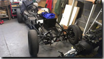
Having worked all over the Christmas and New year period I had a week off work so made a start on prepping the engine for removal. I was hoping that I could remove the exhaust manifold from the engine and twist it out of the way without having to remove the sidepod so I could lift the engine out but fell at the first hurdle when one of the nuts on the manifold would not turn and just started to round off. The only thing left to do was remove the side pod and exhaust. With those bits removed I disconnected all the other items connected to the engine and also removed the bonnet to give clearance to take the engine out.
Splitting the engine and gearbox
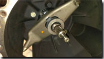
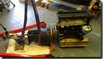
Getting the engine out was fairly easy using my engine crane and once on the floor, removed the clutch release bearing, clutch pivot arm and then the bell housing. Looking inside the bell housing there was very little dirt or debris inside meaning the dust plate I had made was doing its job of stopping rubbish from getting inside the bell housing and also no oil reside so there is no leaks from the crank leaking into the bell housing or oil leaking from the gearbox either, which is a good sign and meant the clutch had not been contaminated and require changing while I had the gearbox off.
While the gearbox was off I removed the top cover and inspected the gears and also topped up the gearbox oil which was probably only about 100ml. With the cover off I also double checked the breather hole was clear which has been known to become blocked and is often a cause of oil leaks past the front and rear oil seals.
Refitted
Once the gearbox and engine were back together (with the gasket fitted this time) I enlisted the help of Chris, my eldest and Mrs Martin as an extra pair of hands and eyes to assist me with refitting the engine back in. Once hung in it took me a further day to get everything reconnected and squared away but overall everything went well including refitting the side pod which I was dreading but actual went back on okay.
With the fluid levels restored and the engine running well with no apparent leaks, I took it for a quick blast around on some very slippery roads just to make sure everything was running okay. Four days work to change a gasket but fingers crossed that's the last of the leak. Roll on some good dry weather.
Back to top


_sml.jpg)
.jpg)
-sml.jpg)
.jpg)
.jpg)
.jpg)
.jpg)
.jpg)
.jpg)
.jpg)
.jpg)
.jpg)
.jpg)
.jpg)
.jpg)
.jpg)
.jpg)
.jpg)
.jpg)
.jpg)
.jpg)
.jpg)
.jpg)
_sml.jpg)
_sml.jpg)
_sml.jpg)
_sml.jpg)
_sml.jpg)
_sml.jpg)
_sml.jpg)
_sml.jpg)
_sml.jpg)
_sml.jpg)
_sml.jpg)
_sml.jpg)
_sml.jpg)
_sml.jpg)
_sml.jpg)
_sml.jpg)
_sml.jpg)
_sml.jpg)
_sml.jpg)
_sml.jpg)
_sml.jpg)
_sml.jpg)
_sml.jpg)
_sml.jpg)
