Wiring
Rather than using the wiring loom from the Sierra donor or one from a Mondeo which would make the engine wiring a bit easier I settled on getting a new purpose built version from Premier Wiring Systems. The advantages of this are that the loom only comes with the components you need and also the wiring is all new and so the problems that can arise from using a used loom can hopefully be avoided.
Premier Wiring Loom
[Update - Alan is now semi retired in Spain although he does still provide help via email and his contact number which is a UK number. Joyce is now running the UK side of the business and they have an E-bay shop for their looms and other parts for kitcars - Premierwiring7 - Ebay shop]
I contacted Alan at Premier Wiring Systems before placing the order for my loom as I wanted to discuss a few things with him such as wiring in a relay and wires for Day Running lights and the provision for the inclusion of an immobilsier. Alan was happy to included these items into the loom and didn't even charge me anymore for doing this. Once the loom arrived I read through the instructions which give details or where everything is located and how it should be wired up to the items located around the car. The next thing I did was trace every wire using the instructions and labeled every end so I would know what went where.
On a few occasions I have had questions with some connections or where the instructions don't seem clear but you can either email or give Alan a ring and he'll call you back and talk you through things.
The Premier wiring loom that I bought was specifically designed to be used with the Sierra stalk controls so the instructions guide you to each pin on these, and its just a matter of crimping on spade connectors to each end and using a connector block to connect them together.
So far I have just slaved the loom into position and tested things out but I cannot make the final terminations and cut the wires to the correct length until the main body tube has been fitted as the loom needs to be threaded through this and I am not completely sure of where it needs to be finally positioned
Zetec Wiring Loom
For now, to get the car running well and to get it through the IVA test the plan is to use the standard Zetec/Mondeo wiring loom and ECU and connect certain parts of that to the Premier loom as required using some guides provdied by big_wasa and Turnipfarmer from the Locostbuilders website.
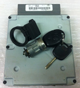
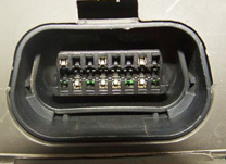
To do all this what you need is the wiring loom that is connected to the Zetec engine and also the loom that connects to the ECU which on the Mondeo is located at the rear offside of the engine bay. You will also need to trace the wiring of this loom and at the other end of the engine bay near the fuse box is the 42pin c2513 plug and the connector that connects this to the car loom. Cut as much of this off as you can as this will be used to wire up to the loom. Obviously you will also need the ecu but you also need to ensure you get PATS sensor which is located around the key barrel and also the key that suites this sensor and ECU, otherwise none of this will work. Another useful part to get is the OBD connector which will allow you to carry out diagnostics on the engine.
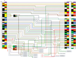
Now as there are so many variations of the zetec installation and there can be changes to wiring colours it is best to strip the loom back to the wires and double check each one. Having done that you can make sure you are getting the correct wire for the connections needed and cross checking mine to big_wasa's and Turnipfarmers there were few differences in wire colors but the pinouts are the same on the plugs. Best to strip back and trace each wire to each pin which is what I have done, this can take some time but at least you know each wire is good and you can also make a diagram for later use should you need it. I started with an Excel sheet with the colours on and then made this into a wiring diagram using Visio. PDF Version available here (This is specific to the year and model of Mondeo loom that I am using and can vary year on year. I will not be held responsible for any damaged caused by using this diagram it is purely for guidance only and your specific loom should be checked before use).
Routing the Loom
Once I had sorted out most of the wiring loom for the engine I used some crimps to connect these up to the main car loom and power things up ready for trying the engine out. Switching on the power the LED light came on steady and the fuel pump ran for a second and then switched off as it should do. After a couple of cranks of the engine with the Ignition coil disconected to make sure the engine wouldn't fire so I could ensure the oil had been circulated I reconnected the coil and after two more cranks the engine fired into life and sat idling just fine. To be honest I was expecting it to be a bit more difficult than that but very happy it would start and run first time.
Now that was sorted I just needed to decide on the routing of the cables but without the bodywork available at this time I left the cable runs as long as possible and didn't completely terminate all the connections incase I need to extend or cut them down once the final positioning had been chosen. Initially I thought about running the cable through the top of the tunnel panel and forward and back through the tunnel as needed but once I did finally have the bodywork and could see where I needed to position the heater it was obvious that this route would be far from ideal.
The only real option was to route the loom out through the front scuttle panel and into the engine bay and then send the cables through the tunnel to the rear and the engine and front section along the chassis rails to the front. WIth this routing decided upon I then layed the loom out in the exact position it needed to be and then started to splice the cables together and covering with heat shrink tubing. In the engine bay and down through the tunnel I also covered the cable with convoluted tubing as added protection.
Rear wiring
Running the loom to the rear of the car I routed the cables through the tunnel and clipped it to the oposite side to the fuel lines. This then runs out the top of the tunnel over the differential and splits off left and right to the lighting, fuel pump and fuel tank contents. I have used bright LED lamps at the rear including a combined rear fog and reverse lamp and also wiring for a third high level brake light.


.jpg)
.jpg)
.jpg)
.jpg)
.jpg)
.jpg)
.jpg)


_sml.jpg)
_sml.jpg)
-sml.jpg)
-sml.jpg)
-sml.jpg)
_sml.jpg)
-sml.jpg)
-sml.jpg)
_sml.jpg)
_sml.jpg)
_sml.jpg)
_sml.jpg)
sml.jpg)
sml.jpg)
